
PVC Extrusion Troubleshooting: 15 Common Defects & Solutions
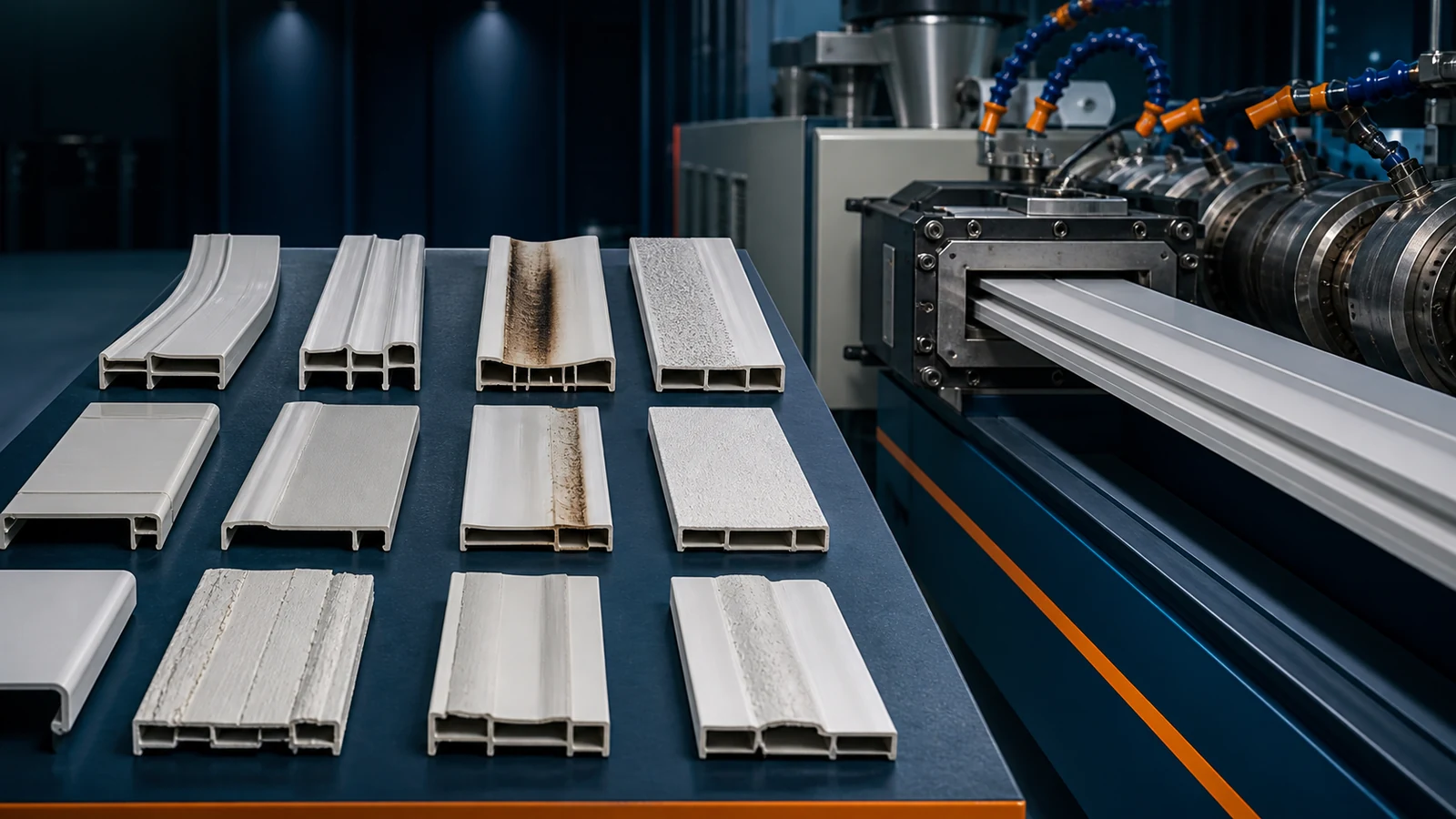
Every PVC extrusion line produces defects. The difference between a profitable operation and a marginal one is how quickly and accurately those defects are diagnosed and corrected. A single shift of unsolved production problems on a PVC wall panel line or foam board line can generate US$2,000–5,000 in scrap.
This troubleshooting guide organizes 15 common PVC extrusion defects by symptom category, identifies the most likely root causes, and provides a systematic diagnostic sequence. Follow the diagnostic order—don't jump to conclusions. Most defects have multiple possible causes, and fixing the wrong one wastes time and material.
Category A: Surface Defects
Defect 1: Sharkskin (Surface Roughness / Melt Fracture)
Symptom: Regular, fine-scale surface roughness perpendicular to extrusion direction, resembling sharkskin. Profile looks uniformly "grainy" or "orange-peel" rather than smooth.
| Root Cause | Diagnostic Check | Corrective Action |
|---|---|---|
| Die temperature too low; melt skin too viscous at die exit | Check die lip temperature with probe pyrometer; compare to setpoint | Increase die lip temperature by 5–10°C; wait 5 min for stabilization |
| Line speed too high for die land length (excessive draw-down) | Reduce line speed by 10% and observe if sharkskin reduces | Reduce line speed or increase die land length (tooling change) |
| Insufficient external lubricant; melt sticking to die land | Check motor load trend (rising load suggests sticking) | Increase external lubricant by 0.1–0.2 phr; verify proper grade |
Defect 2: Die Lines (Longitudinal Streaks/Grooves)
Symptom: Continuous lines or grooves running parallel to extrusion direction along the profile surface. One or multiple lines; may appear and disappear intermittently.
| Root Cause | Diagnostic Check | Corrective Action |
|---|---|---|
| Scratch or burr in die land area | Stop line, disassemble die, inspect land surface under magnification | Polish die land with diamond paste (1–3 μm); remove burr |
| Foreign particle (degraded PVC, metal, sand from CaCO3) stuck in die | Look for a "tail" of degraded material extending from the line origin | Purge with purging compound; clean die; check CaCO3 purity |
| Plate-out deposits accumulating at die lip | Stop line briefly, inspect die lip; scrape test | Adjust external lubricant; clean die; increase die lip temperature |
Defect 3: Gloss Variation (Glossy & Matte Patches)
Symptom: Alternating glossy and matte bands or patches along the profile. More common in wide profiles and sheets.
| Root Cause | Diagnostic Check | Corrective Action |
|---|---|---|
| Uneven cooling in calibration tank; differential shrinkage | Check calibration tank water temperature uniformity (top vs. bottom) | Improve water circulation in tank; add spray bars for uniform cooling |
| Surging (pulsating output) causing varying contact with calibrator | Measure profile weight per meter at 1-minute intervals; check for variation >±2% | Diagnose surging root cause (see Defect 8) |
| Die temperature imbalance across width/cross-section | Check all die heater zones; thermography of die exterior | Balance die zone temperatures; replace dead heater bands |
Category B: Dimensional Defects
Defect 4: Wall Thickness Variation
Symptom: Profile wall thickness varies; may be consistently thicker on one side (die centering issue) or vary along the length (surging). For window profiles, wall thickness tolerance is typically ±0.1–0.2 mm.
| Root Cause | Diagnostic Check | Corrective Action |
|---|---|---|
| Die not centered (mandrel/tip off-center) | Measure wall thickness at four points (0°, 90°, 180°, 270°) around profile | Adjust die centering bolts; equalize wall thickness distribution |
| Uneven melt flow in die manifold | Check for blocked flow channels; inspect die disassembly | Clean die flow channels; adjust restrictor bars (for sheet dies) |
| Vacuum calibration uneven (one side pulls more) | Check vacuum slot placement and vacuum level across calibrator | Balance vacuum distribution; clean vacuum slots |
Defect 5: Warpage / Bowing (After Cooling)
Symptom: Profile curves or bows when placed on a flat surface after cooling. Longitudinal bowing (banana shape) or transverse warping (cup shape).
| Root Cause | Diagnostic Check | Corrective Action |
|---|---|---|
| Asymmetric cooling: one side of profile cools faster | Check temperature of each calibrator section; use contact thermometer on profile exiting tank | Equalize cooling water temperature and flow; add spray bars on hot side |
| Residual stress from uneven melt flow in die | Cut profile cross-section; heat to 120°C for 10 min; observe warpage direction | Fix die centering; adjust die land lengths to equalize flow resistance |
| Puller misalignment (profile pulled at an angle) | Check puller belt alignment relative to die centerline | Align puller precisely with die exit; check belt tension even left/right |
Defect 6: Shrinkage (Post-Extrusion Dimensional Change)
Symptom: Profile dimensions reduce after cooling to room temperature, beyond expected thermal contraction. Can cause length to fall below tolerance (e.g., 3m profile measures 2.985m after 24h).
| Root Cause | Diagnostic Check | Corrective Action |
|---|---|---|
| Insufficient gelation; internal stress frozen in | Acetone immersion test: poor gelation = profile swells/crazes in acetone | Increase barrel temps in plastication zone; reduce screw speed |
| Excessive draw-down (stretching the melt) | Calculate haul-off speed / theoretical die exit speed ratio >1.05 | Reduce haul-off speed or increase extruder output to match |
| Cooling too fast (quenching locks in orientation) | Measure profile surface temp at calibrator exit; >40°C suggests too cold | Increase cooling water temperature (to 20–30°C, not ice-cold); use gradual cooling |
Category C: Bulk/Structural Defects
Defect 7: Poor Gelation (Unmelted Particles, Brittle Product)
Symptom: Profile surface shows unmelted PVC particles (like fine sand). Profile is brittle, splinters on impact. Acetone test shows surface crazing/cracking.
| Root Cause | Diagnostic Check | Corrective Action |
|---|---|---|
| Processing temperature too low | Check melt temperature at die exit; should be 185–195°C for uPVC | Increase barrel Zones 2–3 by 5–8°C; verify setpoint vs. actual |
| Screw speed too high; insufficient residence time | Reduce screw speed by 15% and check if gelation improves | Reduce screw RPM; increase temperature instead to maintain output |
| Insufficient processing aid (ACR) in formulation | Review formulation; ACR below 1 phr in rigid PVC is generally insufficient | Increase ACR processing aid to 1.5–3.0 phr |
Defect 8: Surging (Pulsating Output)
Symptom: Cyclic variation in extruder output, visible as periodic thickness or weight-per-meter fluctuation. Motor load (amperage) oscillates in a rhythmic pattern (cycle 5–30 seconds).
| Root Cause | Diagnostic Check | Corrective Action |
|---|---|---|
| Bridging in feed throat (material not flowing into screw evenly) | Observe material level in hopper; listen for "starving" sound (screw running dry intermittently) | Reduce Zone 1 temperature by 5–8°C; install hopper vibrator or crammer feeder |
| Inconsistent bulk density of dry blend | Check bulk density of several samples from same batch; variation >±5% | Improve hot-mixing consistency; verify cooling mixer operation |
| Worn screw/barrel causing back-flow variation | Measure output at fixed RPM; compare to historical benchmark | Measure screw/barrel clearance; if >2x original clearance, replace |
Defect 9: Degradation (Yellowing, Browning, Black Specks)
Symptom: Profile shows color change from white/cream to yellow, then brown, then black. Black specks indicate severe localized degradation. Acrid HCl odor near the die.
| Root Cause | Diagnostic Check | Corrective Action |
|---|---|---|
| Melt temperature too high (>200°C for rigid PVC) | Probe melt temperature at die exit | Reduce all zones by 5–8°C; reduce screw speed to lower shear heating |
| Residence time too long (dead spots in die/adapter) | Purge with color change material; observe where color change is slowest (dead spot location) | Clean or modify die to eliminate dead spots; streamline adapter flow path |
| Insufficient thermal stabilizer | Review formulation; verify stabilizer dosage; check stabilizer quality (supplier change?) | Increase stabilizer by 0.5–1.0 phr; test new stabilizer batch |
The "color timeline" of PVC degradation is your best diagnostic: white → cream = early degradation, adjustable; yellow = significant degradation, stop and correct within 5–10 minutes; brown = advanced degradation, purge immediately; black = catastrophic, purge and possibly disassemble to clean.
Category D: Hollow/Foamed Product Defects
Defect 10: Non-uniform Foam Cell Structure
Symptom: PVC foam board shows varying cell size: large cells near surface, small or no cells in center, or vice versa. Cross-section shows irregular cell distribution.
| Root Cause | Diagnostic Check | Corrective Action |
|---|---|---|
| Uneven temperature: surface cools faster than core, inhibiting surface foaming | Cut cross-section; inspect cell size gradient from surface to core | Increase die temperature; reduce calibrator cooling; add nucleating agent (nano-CaCO3) |
| Foaming agent decomposition timing off | Check if foaming agent decomposition temperature matches processing temperature | Adjust foaming agent type (ADC 160°C, NaHCO3 150°C) or use endothermic/exothermic blend |
| Pressure drop in die insufficient (premature foaming inside die) | Check for bubbles in melt before die exit (indicates premature foaming) | Increase die land length to maintain higher internal pressure; reduce melt temperature |
Defect 11: Surface Craters / Pinholes in Foam Board
Symptom: Small craters, pinholes, or collapsed bubbles on the foam board surface. More common with Celuka process when the surface skin is too thin.
| Root Cause | Diagnostic Check | Corrective Action |
|---|---|---|
| Moisture in formulation (CaCO3 absorbs ambient moisture) | Check CaCO3 moisture content; >0.3% is problematic for foaming | Pre-dry CaCO3 at 90°C for 2–3h before hot-mixing |
| Volatiles from lubricant or processing aid | Check TGA of lubricants/processing aids; look for weight loss at processing temperature | Switch to thermally stable lubricant grades (high-purity paraffin, EBS rather than stearic acid) |
| Celuka skin too thin; bubbles break through surface | Measure skin thickness from cross-section; Celuka skin should be 0.3–0.8 mm | Increase calibrator cooling rate at surface (water at 10–15°C); reduce die lip opening |
Category E: Calibration & Cooling Defects
Defect 12: Chatter Marks (Periodic Transverse Ridges)
Symptom: Series of regular, closely spaced transverse ridges or lines across the profile surface, like a washboard. Periodicity matches puller belt or calibrator vibration frequency.
| Root Cause | Diagnostic Check | Corrective Action |
|---|---|---|
| Puller belt slipping/sticking (stick-slip motion) | Listen for rhythmic squeaking from puller; check belt wear | Adjust puller pressure; replace worn belts; clean belt surface |
| Vacuum fluctuation in calibrator (pump cycling) | Check vacuum gauge; oscillation >±0.01 MPa | Install vacuum buffer tank; check vacuum pump for wear; service vacuum regulator |
| Profile sticking and releasing in calibrator | Check if profile leaves drag marks in calibrator | Increase calibrator cooling; polish calibrator surface; increase external lubricant |
Defect 13: Water Marks / Cooling Stains
Symptom: Milky white stains or blotches on the profile surface after cooling, especially visible on dark-colored profiles.
| Root Cause | Diagnostic Check | Corrective Action |
|---|---|---|
| Water quality: high mineral content (hard water) leaves deposits | Test cooling water hardness; TDS >200 ppm may cause staining | Use softened/deionized water for cooling; install water treatment |
| Cooling water temperature too cold (thermal shock) | Measure calibrator water temperature; <10°C is too cold for most profiles | Use tempered water at 15–25°C; start with warm water at calibrator entry, cold at exit |
Category F: Multi-Layer / Co-extrusion Defects
Defect 14: Layer Delamination (Co-extrusion)
Symptom: Layers of a co-extruded profile separate. Cap layer peels from core. May occur at the die exit (immediate) or after cooling (delayed).
| Root Cause | Diagnostic Check | Corrective Action |
|---|---|---|
| Melt temperature mismatch at merge point (>15°C difference) | Check both extruder melt temperatures before merge | Adjust temperatures to be within 10°C of each other at merge point |
| Incompatible materials (e.g., PP cap on PVC core without tie-layer) | Verify material compatibility; check if tie-layer is specified | Use compatible polymer pair or add appropriate tie-layer adhesive |
| Contamination at interface (moisture, degraded material, oil) | Inspect die combining section for contamination | Clean combining section thoroughly; verify material handling prevents contamination |
Defect 15: Plate-Out (Die Lip Build-up)
Symptom: White, waxy or powdery deposit accumulating on the die lips over time. Deposit grows and eventually detaches, causing surface blemishes or die lines. Plate-out contains lubricants, stabilizer decomposition products, and TiO2.
| Root Cause | Diagnostic Check | Corrective Action |
|---|---|---|
| Excessive external lubricant; lubricant exudes at die exit | Analyze plate-out deposit (FTIR); presence of PE wax and stearates confirms lubricant excess | Reduce external lubricant by 0.1–0.3 phr; switch to higher molecular weight lubricant |
| Die lip temperature too cold (lubricant condenses) | Check die lip temperature vs. die body; >5°C colder promotes plate-out | Increase die lip temperature by 5–10°C relative to die body |
| Incompatibility between stabilizer and lubricant system | Review stabilizer-lubricant interaction; some Ca-Zn stabilizers react with stearic acid | Use one-pack stabilizer-lubricant system from same supplier; reformulate |
Systematic Diagnostic Approach
When a defect appears, follow this diagnostic sequence before taking action:
- Define the defect precisely: Describe what you see, not what you think the cause is. Take photos. Measure dimensions.
- Is it continuous or intermittent? Continuous defects point to die/calibrator/tooling issues. Intermittent defects point to material variation, surging, or temperature cycling.
- Is it periodic? If yes, measure the period. Compare to screw RPM, puller belt circumference, and calibrator vacuum pump cycle to identify the source.
- Check the easy things first: Temperature setpoints vs. actual, material level in hopper, vacuum level, cooling water flow/temperature, puller belt condition.
- Change one variable at a time: Adjust temperature by 5°C OR screw speed by 2 RPM OR line speed by 5%—never multiple changes at once.
- Wait for stabilization: After any change, wait 10–15 minutes for the system to reach a new steady state before evaluating the effect.
Production operators who jump to "let's change the formulation" as the first troubleshooting step are usually wrong. 70% of extrusion defects have a process or equipment root cause, not a formulation root cause. Exhaust process adjustments before changing the recipe.
Persistent Extrusion Problem?
Our process engineers provide remote and on-site troubleshooting for PVC extrusion lines worldwide. Send us photos and process data for a rapid diagnosis.
Get Technical SupportRelated Articles
- PVC Temperature Control Extrusion Guide
- PVC Die Design for Profiles and Sheets
- PVC Formulation Guide for Profile Extrusion
- Screw & Barrel Maintenance Guide
- PVC Co-extrusion Technology Guide
Conclusion
Effective troubleshooting is a systematic discipline, not guesswork. The best extrusion operators don't know the answer to every defect—they know the right diagnostic question to ask. When a defect appears: define it precisely, check if it's periodic, eliminate the simple causes first, change one variable at a time, and wait for stabilization. And remember: most defects are process-related, not formulation-related. Before calling your material supplier, check your temperatures, screw speed, and calibrator setup.