
PVC Co-extrusion Technology Guide: Multi-Layer Profile & Sheet Extrusion
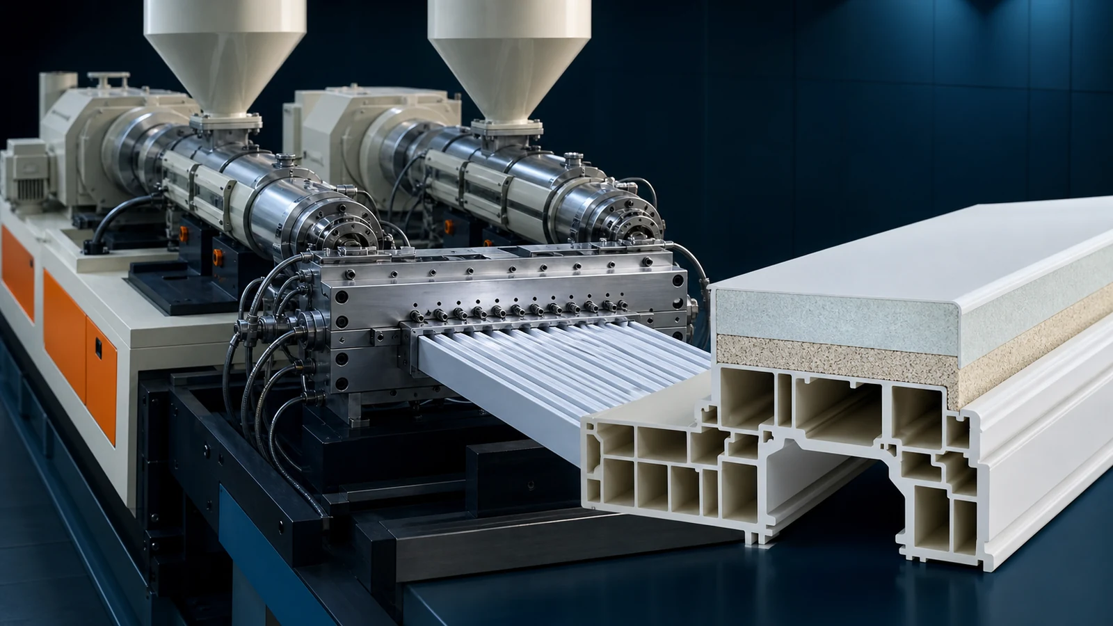
Co-extrusion is the process of combining two or more polymer streams into a single, multi-layer product in one continuous operation. For PVC extrusion, co-extrusion unlocks capabilities that single-layer extrusion cannot: a premium weatherable cap layer on a cost-optimized core, a recycled-material core hidden inside a virgin skin, or a rigid substrate with a flexible sealing lip—all produced in a single pass. From window profiles with co-extruded gaskets to foam boards with a hard surface skin, co-extrusion is the technology that makes high-performance PVC products commercially viable.
This guide covers co-extrusion die technology, material pairing strategies, process control, and troubleshooting.
1. Co-extrusion Configurations
Co-extrusion systems are defined by how and where the melt streams combine:
| Configuration | How It Works | Layer Thickness Control | Typical Applications |
|---|---|---|---|
| Feedblock co-extrusion | Melt streams merge in a feedblock before entering a single-manifold die | Moderate (±10% uniformity) | Sheet/board; 2–3 layers; cap layer >10% of total thickness |
| Multi-manifold die | Each layer has its own die manifold; layers merge at the die exit | Excellent (±3% uniformity) | Profiles; thin cap layers (0.1–0.5 mm); 2–5 layers |
| Adapter/combiner system | Separate adapters feed individual melt streams into a distribution combiner before the die | Good (±5% uniformity) | Complex profiles; asymmetric layer distribution |
Feedblock vs Multi-Manifold: When to Use Which
Feedblock is simpler and cheaper (US$5,000–15,000 adder) but offers less precise layer control. Use for sheet/board co-extrusion where layer thickness uniformity of ±10% is acceptable.
Multi-manifold die is the gold standard for profile co-extrusion (US$20,000–50,000 adder). Each layer has independently adjustable melt distribution, enabling precise control of thin cap layers (as thin as 0.1 mm) uniformly around complex profile cross-sections. This is the only viable approach for co-extruded window profile gaskets and thin weatherable cap layers.
2. Material Pairing Strategies
Co-extrusion's value comes from combining materials with complementary properties. The most common pairings in PVC extrusion:
| Layer Structure | Cap/Skin Material | Core Material | Benefit | Applications |
|---|---|---|---|---|
| Weatherable cap / cost-optimized core | Weatherable PVC compound (high TiO2, UV package, ASA or PMMA) | Standard uPVC (lower TiO2, higher filler) | Cap provides 20+ year outdoor durability; core cost is 15–25% lower | Window profiles, siding, fascia, outdoor decking |
| Virgin skin / recycled core | Virgin PVC compound | Post-industrial recycled PVC (regrind) | Surface quality of virgin PVC; core uses 30–70% recycled material | Non-visible profiles, cable trunking, sub-flooring |
| Hard skin / foamed core | Solid rigid PVC | Foamed PVC (0.55–0.70 g/cm3) | Smooth hard surface + lightweight core at 25–35% weight reduction | Celuka foam boards, door panels, furniture boards |
| Flexible lip / rigid body | Soft PVC / TPE | Rigid PVC | Integrated flexible seal eliminates separate gasket insertion step | Window profiles with co-extruded gaskets |
| Colored cap / white core | Colored/wood-grain PVC compound | White PVC | Color only in surface layer; 60–80% reduction in pigment cost | Colored profiles, wood-grain finishes, decorative trims |
| High-gloss cap / matte core | High-gloss PVC (low filler, acrylic-modified) | Standard PVC | Premium gloss surface without full-body premium formulation | Furniture profiles, edge banding, decorative moldings |
3. Co-extrusion Die Design Principles
Melt Viscosity Matching
The single most important rule of co-extrusion: the melt viscosities of adjacent layers must be closely matched at the merge point. If two melts with different viscosities meet at the combining section, the lower-viscosity melt will encapsulate the higher-viscosity melt, causing layer thickness instability and interfacial distortion.
Practical viscosity matching: Aim for a viscosity ratio (lower/higher) of 0.67–1.5 at the processing shear rate (typically 100–500 s-1 in the die land region). If the viscosity ratio exceeds 2:1, use the encapsulation principle to your advantage by designing the lower-viscosity layer to be the outer one.
Temperature Control at the Merge Point
The two melt streams should arrive at the merge point at temperatures within 10–15°C of each other. A cold stream meeting a hot stream creates an immediate viscosity mismatch and interfacial instability. Use independently heated adapters for each extruder, and position the merge point as close to the die exit as practical to minimize residence time after combining.
Interfacial Stability
For a stable interface between layers, the two melts must experience similar shear stress at the interface. This is achieved by:
- Designing the die land length to equalize the average flow velocity of both layers at the merge point
- Using a combining geometry with a gradual convergence angle (<30°) rather than an abrupt junction
- Maintaining sufficient back-pressure (5–15 MPa) to suppress melt fracture at the interface
4. Co-extruder Sizing & Configuration
The co-extruder (for the cap/skin layer) is always smaller than the main extruder. Sizing rules:
| Cap Layer Thickness (% of total) | Co-extruder Size (as % of main extruder output capacity) | Typical Setup (main + co-ex) |
|---|---|---|
| 5–10% (thin cap) | 10–20% | SJZ 65/132 + SJZ 35/75 or SJ 45/25 single-screw |
| 10–20% (standard cap) | 20–35% | SJZ 65/132 + SJZ 45/90 or SJZ 51/105 |
| 20–40% (thick skin / dual-layer) | 35–60% | SJZ 80/156 + SJZ 55/110 or SJZ 65/132 |
| >40% (equal layers) | 60–100% | Two identical extruders (dedicated co-extrusion line) |
Co-extruder type: For thin cap layers (5–15%), a single-screw extruder (SJ 30–45) is often sufficient and more economical. For thicker skins or formulations with higher viscosity (e.g., weatherable compound with high TiO2), a small conical twin-screw (SJZ 35–51) provides better melt homogeneity.
5. Process Parameters for Co-extrusion
Temperature Profile Coordination
The main and co-extruder temperature profiles must be coordinated, not identical. A typical setup for a rigid PVC cap on rigid PVC core:
| Extruder | Zone 1 | Zone 2 | Zone 3 | Zone 4 | Adapter |
|---|---|---|---|---|---|
| Main (core) | 160°C | 168°C | 172°C | 170°C | 168°C |
| Co-extruder (cap) | 165°C | 172°C | 175°C | — | 172°C |
The co-extruder runs 3–5°C hotter because:
- The smaller screw generates less shear heat
- The thin cap layer cools faster in the die (higher surface-to-volume ratio)
- The cap compound often contains less lubricant (to maintain surface properties), requiring slightly higher processing temperature
Pressure Balancing
The melt pressure of both streams at the merge point must be equal (±0.5 MPa). Pressure imbalance causes the higher-pressure stream to push into the lower-pressure stream's flow channel, disrupting the interface and creating layer thickness variation. Use separate pressure transducers at each adapter and adjust screw RPM or back-pressure valves to balance.
6. Adhesion Between Layers
Interlayer adhesion in PVC co-extrusion is generally excellent when both layers are PVC-based—the same polymer chains diffuse across the interface when the melts are above Tg (80°C) and under pressure. However, problems arise with dissimilar materials:
- PVC to ASA/PMMA cap: These are different polymers with limited interdiffusion. Use a tie-layer (acrylic copolymer adhesive) or ensure the interface temperature exceeds 190°C at the merge point for maximum interdiffusion.
- PVC to TPE/soft PVC: Adhesion is generally good because plasticized PVC and TPE are compatible. Ensure the soft layer is fully gelled before the merge point.
- PVC to PE/PP: These are incompatible. A co-extrudable adhesive tie-layer (maleated PE or EVA-based) is mandatory.
Test interlayer adhesion using a 180° peel test (ASTM D903). For window profiles with co-extruded cap layers, adhesion strength should exceed 4 N/mm. Values below 2 N/mm indicate insufficient interfacial bonding and will lead to delamination in service.
7. Common Co-extrusion Defects
| Defect | Cause | Solution |
|---|---|---|
| Layer thickness variation (wavy interface) | Melt pressure imbalance; viscosity mismatch; pulsating output from one extruder | Balance melt pressures; match viscosities; check screw/Motor of surging extruder |
| Encapsulation (one layer wraps around the other) | Large viscosity ratio (>3:1); one melt much lower viscosity | Reduce temperature of low-viscosity melt to increase viscosity; adjust formulations for closer viscosity match |
| Interfacial instability (zigzag/wavy layer boundary) | Excessive shear stress at interface; convergence angle too steep in combining section | Reduce throughput; modify combining geometry to shallower angle; increase die land length |
| Delamination (layers separate) | Insufficient interfacial temperature; incompatible materials; contamination at interface | Increase merge-point temperature; verify material compatibility; clean die combining section |
| Cap layer too thick/thin in corners | Non-uniform melt distribution in cap layer manifold; die design inadequate for complex cross-section | Adjust restrictor bars/manifold tuning; redesign cap layer flow channel for uniform thickness around profile perimeter |
| Gels/unmelts at interface | Cap layer material not fully gelled before merge; cold spots in co-extruder adapter | Increase co-extruder temperature; check for dead spots in adapter; increase co-extruder screw RPM for more shear work |
Planning a Co-extrusion Project?
Our engineering team designs complete co-extrusion systems—extruder pairing, die design, and process optimization—tailored to your product.
Discuss Your ProjectRelated Articles & Products
- PVC Die Design for Profiles and Sheets
- PVC Temperature Control Extrusion Guide
- PVC Stabilizer Selection: Ca-Zn vs Organotin
- Products: PVC Window Profile Machine | PVC Foam Board Machine | PVC Edge Banding Machine
Conclusion
Co-extrusion is the technology that makes PVC profiles and sheets competitive with higher-cost materials. The ability to put a weatherable, high-gloss, or colored cap layer on a cost-optimized core is what allows PVC window profiles to compete with aluminum and wood, and PVC foam boards to compete with plywood and MDF. The key technical challenges—viscosity matching, pressure balancing, and interfacial stability—are well understood and manageable with proper die design and process control. The capital investment in a co-extrusion system (typically US$30,000–70,000 adder over a single-layer line) pays back through material cost savings (15–25% on the core formulation) and product differentiation that commands higher margins.